What’s this blog about?
Lately, I’ve been quite interested on the hardware side of computer systems, and since all open-source SBCs that I can find are all ARM-based, I guess it is time to learn how ARM-based computers boot.
Since I already have a Raspberry Pi (Rpi) laying around, I thought it might be a good idea to use it as a practice - by default, Rpi uses proprietary bootloaders. So to test my understanding, I’ll try to modify its boot sequence using open-source embedded firmware, namely u-boot.
Needless to say, I am writing this blog to document my experience modifying Rpi’s boot sequence.
In a nutshell: How your average ARM computers boot
ARM computers boot differently from x86s, and in my opinion, ARMs’ are simpler. Although exact details vary from board to board, in general, here’s how the boot process works:
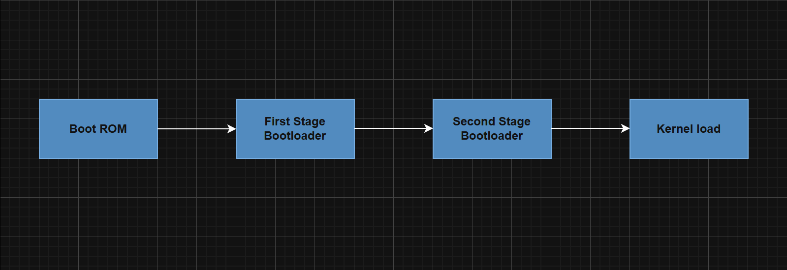
When we first boot our computer, a binary that resides inside the internal flash of the System on Chip (SoC) called the Boot ROM (BROM) will execute. Its one job is to locate the first stage bootloader that resides inside external memory (SD, eMMC, NAND chip, etc.).
How does the BROM binary know where the first stage bootloader is?
Well, the BROM binary is set by the manufacturer to look at specific location of the memory and it is our job as developers to ensure that the bootloader is located at the right place for a given SoC. Different manufacturers set their BROM binary for each board differently. Here are some examples for your reference:
| Manufacturer | | Details | | link |
|---|---|---|
| Allwinner | | 8KB offset | | https://linux-sunxi.org/Bootable_SD_card |
| Rockchip | | 256KB offset | | https://lxr.missinglinkelectronics.com/uboot/doc/README.rockchip |
| NXP | | 1KB offset | | https://docs.u-boot.org/en/v2025.01/board/ti/am335x_evm.html |
Once the BROM binary locates the first stage bootloader, it will then pass control to the first stage bootloader, whose job is to do some initializations, such as clocks & DRAM. Once completed, it passes control to the second stage bootloader.
the second stage bootloader can be considered as the main bootloader. Its job is to make preparations (such as finding the device tree) & load the kernel and optionally the virtual root filesystem, initramfs.
And that’s it! Once control has been passed to the kernel, the booting process is complete!
You may wonder, what is a device tree? Well, let me answer that with a question:
“Different boards have different hardware layout. How does the OS know the layout of a given device? If computer A has a dedicated GPU while computer B doesn’t, then how will the OS know?”
Well, that’s what a device tree is for. It is essentially a metadata, almost like a JSON file, that describes what components are present, and how they are arranged, in a board. When loading the kernel, the device tree will be passed to the kernel. In x86, you may know this as ACPI table.
How Rpi boots
Next, let’s talk about how Rpi boots. The Rpi that I am using is RPi model 4B, which uses an SoC made by Rockchip that is custom-made for Rpi. At Any rate, Rpi’s boot process is slightly different from how ARM boards boot in general. However, it is still similar:
Let’s walk through the diagram. But before that, I’d like to add that in Rpi, the VideoCore (the “GPU”) is the primary power-on processor. To be honest, I didn’t even know this when I was modifying the boot sequence of my Rpi. I first learned about this when writing this blog (because I cross-check what I am about to write with chatGPT lol).
With that out of the way, let’s begin.
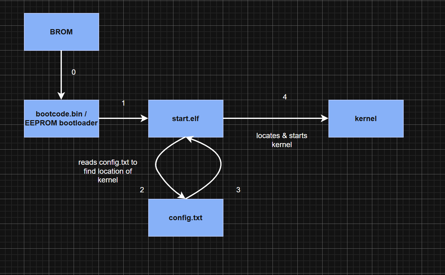
Since the GPU is the primary power-on processor, the BROM binary, or the first stage bootloader, is actually the GPU ROM. Next, depending on the Rpi model, there are two possibilities:
- Rpi 3 and older:
bootcode.bin, thesecond stage bootloader, is loaded. - Rpi 4 and newer:
EEPROM bootloaderwill act as thesecond stage bootloader. Meanwhile,bootcode.binis ignored.
When the second stage bootloader is run, it will locate and load start.elf, which acts as the third stage bootloader. start.elf then looks for a user-defined config file called config.txt to locate the kernel. Once the information about the location is retrieved, it will locate and load the kernel.
And we’re done! the kernel has taken over the computer!
U-boot: THE universal bootloader
Now that we’ve got the basic idea on how Rpi boots, let’s talk about the open-source bootloader I mentioned early on: U-boot. U-boot’s workflow can be summarized as follows:
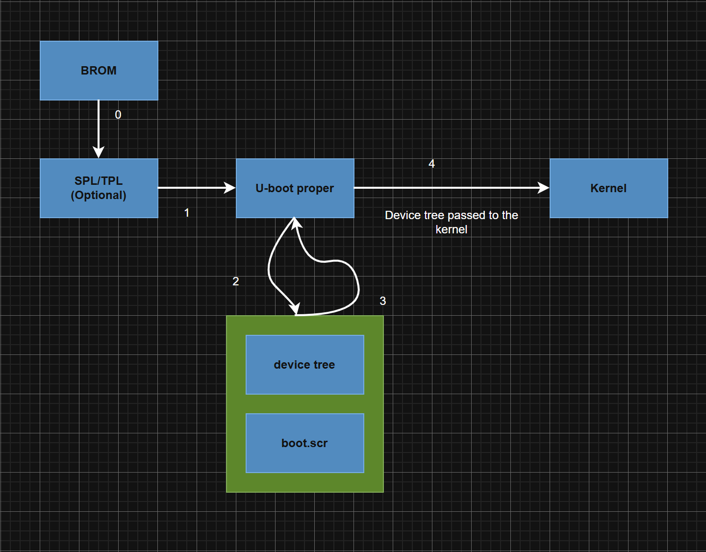
I think by now you can understand the diagram on your own: When a computer boots, the BROM binary acts as first stage bootloader. This is provided by the manufacturer and we cannot modify it whatsoever.
Next, the binary will optionally load the TPL (Tiny Program Loader) / SPL (Secondary Program Loader), which are small-sized bootloader meant for minimal initializations needed by the actual second stage bootloader.
Next, depending on whether you used the TPL/SPL or not, the third stage bootloader or the second stage bootloader, what we call U-boot proper, is loaded.
U-boot proper does many things, among them are:
- Read the user-defined configurations in
boot.scr(similar to Rpi’sconfig.txt) - Retrieve the
device tree
Finally, U-boot proper will load the kernel and passes the device tree information to it.
And that’s it - our computer has booted!
Incorporating U-boot to Rpi
Now that the theory is out of the way, let’s move on to application!
To begin, let’s view the disk (SD card) layout first. To do this, I simply mounted the SD card with the official Raspberry Pi OSimage to a Linux VM and run Fdisk:
root@ubuntu:/dev# fdisk -l /dev/sdb
Disk /dev/sdb: 58.61 GiB, 62914560000 bytes, 122880000 sectors
Disk model: Storage Device
Units: sectors of 1 * 512 = 512 bytes
Sector size (logical/physical): 512 bytes / 512 bytes
I/O size (minimum/optimal): 512 bytes / 512 bytes
Disklabel type: dos
Disk identifier: 0xc636d851

Device     Boot   Start       End   Sectors  Size Id Type
/dev/sdb1         16384   1064959   1048576  512M  c W95 FAT32 (LBA)
/dev/sdb2       1064960 122879999 121815040 58.1G 83 Linux
Here, there are two partitions: /dev/sdb1 and /dev/sdb2. Since /dev/sdb1’s filesystem type is FAT32, it is the boot partition, and that’s where our bootloaders (start.elf and bootcode.bin) as well as our kernel reside within the SD card.
Now that we know where the key binaries are located, we can move on.
Earlier, I mentioned that config.txt is used by start.elf to locate the kernel. Now, let’s see how it is actually implemented. If we view config.txt:
# For more options and information see
# http://rptl.io/configtxt
# Some settings may impact device functionality. See link above for details

# Uncomment some or all of these to enable the optional hardware interfaces
#dtparam=i2c_arm=on
#dtparam=i2s=on
#dtparam=spi=on

# Enable audio (loads snd_bcm2835)
dtparam=audio=on

# Additional overlays and parameters are documented
# /boot/firmware/overlays/README

# Automatically load overlays for detected cameras
camera_auto_detect=1

# Automatically load overlays for detected DSI displays
display_auto_detect=1

# Automatically load initramfs files, if found
auto_initramfs=1

# Enable DRM VC4 V3D driver
dtoverlay=vc4-kms-v3d
max_framebuffers=2

# Don't have the firmware create an initial video= setting in cmdline.txt.
# Use the kernel's default instead.
disable_fw_kms_setup=1

kernel=kernel8.img

# Run in 64-bit mode
arm_64bit=1

# Disable compensation for displays with overscan
disable_overscan=1

# Run as fast as firmware / board allows
arm_boost=1

[cm4]
# Enable host mode on the 2711 built-in XHCI USB controller.
# This line should be removed if the legacy DWC2 controller is required
# (e.g. for USB device mode) or if USB support is not required.
otg_mode=1

[cm5]
dtoverlay=dwc2,dr_mode=host
The line kernel=kernel8.img tells start.elf where the kernel is, relative to the root of the boot partition. If we want to modify the boot sequence in a way that “forces” start.elf to run u-boot instead, we can do the following modification:
kernel=u-boot.bin
device_tree=bcm2711-rpi-4-b.dtb
Next, we need to actually compile u-boot.bin (this doesn’t exist by default in Rpi, mind you.). To do that, we first need to clone u-boot’s repository & choose the branch that we want to use. For my case:
git clone https://source.denx.de/u-boot/u-boot.git
cd u-boot
git checkout v2021.07
Additionally, since my host computer is x86, my VM (Ubuntu 22) doesn’t come with the required ARM toolchain. So I installed them as well, along with u-boot-tools. At any rate, here are the required tools (your distro may or may not have them already):
sudo apt install gcc-aarch64-linux-gnu build-essential bison flex libssl-dev
sudo apt install device-tree-compiler python3 kmod
sudo apt install u-boot-tools
Up next, compilation. But before that, we need to tell the compiler for which Rpi model we want to compile our u-boot for. Fortunately, some developer(s) out there had written config files for different Rpi models. To check:
root@ubuntu:/media/vmware/rootfs/u-boot# cd configs/
root@ubuntu:/media/vmware/rootfs/u-boot/configs# ls | grep rpi
rpi_0_w_defconfig
rpi_2_defconfig
rpi_3_32b_defconfig
rpi_3_b_plus_defconfig
rpi_3_defconfig
rpi_4_32b_defconfig
rpi_4_defconfig
rpi_arm64_defconfig
rpi_defconfig
For me, since I am using Rpi 4b, I’ll be using rpi_4_defconfig.
Now all that’s left is just setting up some environment variables and compile:
export CROSS_COMPILE=aarch64-linux-gnu-
export ARCH=arm
make rpi_4_defconfig
make CROSS_COMPILE=aarch64-linux-gnu- -j$(nproc)
cp u-boot.bin /mount/boot/
And we’re done. u-boot.bin should’ve been compiled by now. Just move it to the root of the boot partition.
Up next, boot.scr. To write one, you need to understand the basics of writing commands on the u-boot terminal. It is a bit too long to explain here, but you can watch Video 1 and Video 2, as well as reading the official u-boot docs for more details.
At any rate, here’s the script that I wrote (Copied from other projects then tweaked a bit :D):
echo welcome to boot.scr!

fdt addr && fdt get value bootargs /chosen bootargs
fatload mmc 0:1 ${kernel_addr_r} Image


echo booting kernel!
booti ${kernel_addr_r} - ${fdt_addr}
Don’t forget to compile:
mkimage -C none -A arm -T script -d boot.cmd boot.scr
Few points worth noting:
kernel_addr_randfdt_addrare default values that have been set during compilation. These tellu-bootwhere it should put thekernelanddevice tree blobon memory. You can overwrite it if you want, though. Just make sure there is no overlap.- I renamed my kernel image to
Image. I didn’t have to - it’s just my personal preference.
And we’re all done! Don’t forget to put boot.scr on the root of boot partition.
Testing
Now, let’s move on to testing!
The easiest way to test whether you have properly modified Rpi’s boot sequence is to simply connect your Rpi to a screen and see the output. Sadly, however, I only use my Rpi in headless configuration, so I never have an external monitor.
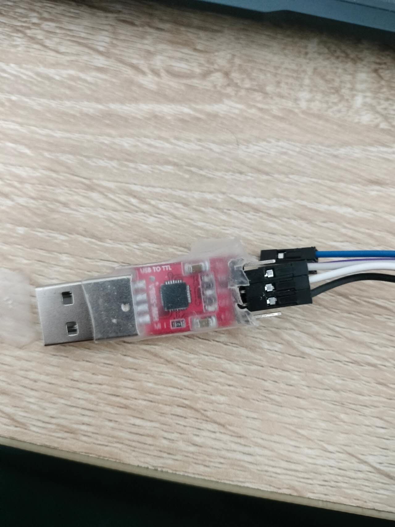
Since I don’t feel like wasting too much money just on this mini-project, I decided to just probe my Rpi via UART. Granted, I still have to spend some money to buy a UART to USB converter, but it is still way cheaper than a proper monitor.
Before we start this stage, let’s add some more things under config.txt:
enable_uart=1
core_freq=250
To be honest, since Rpi operates at stable frequency, I’m not sure why you must set the core frequency - I saw someone else online doing this, and I followed him/her since I thought it adds an extra layer of redundancy.
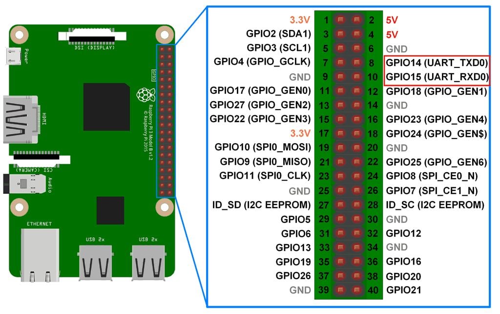
At any rate, you then connect the pins to your Rpi’s GPIO. For my model (Rpi Model 4b), the layout looks as such (credits to ElectronicWings):
After that, you need to hook up the UART to USB converter to your machine (for my case, I mounted it to my VM) and find which virtual filesystem corresponds to your converter. For example, here’s what I did on my VM:
root@ubuntu:/home/vmware# cd /
root@ubuntu:/# ls /dev | grep ttyUSB
ttyUSB0
We will then use screen to monitor the UART comms. For my case:
screen /dev/ttyUSB0 115200
115200 is the baud rate. If you’re wondering where I got that number, I found it online (don’t remember where). Alternatively, to find out on your own (and not rely on the internet!), you can use Logic Analyzer or guess using common baud rates.
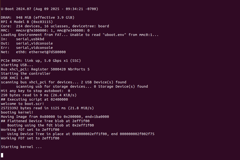
Now, let’s power up the Rpi. Here’s when u-boot loads:
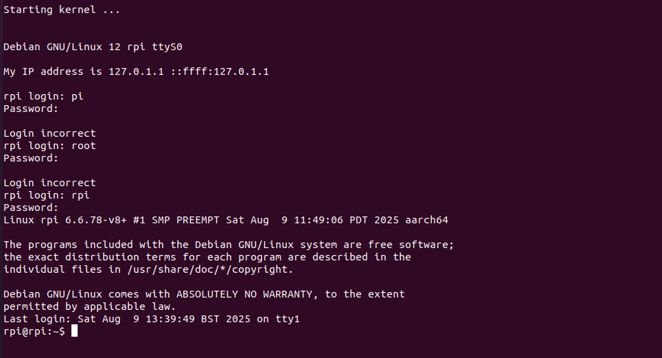
After a while, the kernel finally loads and we can see the login prompt (sorry I forgot my username, haha):
A successful mini-endeavour!
Conclusion
As mentioned earlier, I’ve been interested in hardware development recently and am trying to develop my own ARM-based computer. Coming from Computer Science background, this is a completely new frontier for me and so many things could go wrong: PCB signal integrity issues, component thermal shock from soldering, firmware bug, etc.
Therefore, to minimize my chances of failure, I’ve been testing my understanding on ARM boot process by playing around with my Rpi and I’m happy that in the end, this mini-project has been successful. Up next, aside from the hardware side, I’ll still be doing development on the software side by developing the firmware & OS for the exact processor that I’ll be using (I found a reference board that I can buy at a relatively low cost on TaoBao. Maybe this is the advantage of living in China - everything is available here).
Anyway, this is the end of the blog, see you next time!